
Transcranial Aberration Correction
Phase aberration correction is essential in transcranial histotripsy to compensate for focal distortion caused by the heterogeneity of the intact skull bone. We improved the 2-step aberration correction (AC) method that has been previously presented [1] and developed an AC workflow that fits in the clinical environment, in which the computed tomography (CT)-based analytical approach was first implemented, followed by a cavitation-based approach using the shockwaves from the acoustic cavitation emission (ACE) [2]. A 700 kHz, 360-element hemispherical transducer array capable of transmit-and-receive on all channels was used to transcranially generate histotripsy-induced cavitation and acquire ACE shockwaves. The performance of the 2-step method was tested with 3 excised human calvariums placed at 2 different locations in the transducer array. Results showed that the 2-step AC achieved 90 +/- 7% peak focal pressure compared to the gold standard hydrophone correction. It also reduced the focal shift from 0.84 to 0.30 mm and the focal volume from 10.6 to 2.0 mm cubed on average compared to the no AC cases. The 2-step AC yielded better refocusing compared to either CT-AC or ACE-AC alone and can be implemented in real-time for transcranial histotripsy brain therapy.
Soft Tissue Aberration Correction
In the first clinical trial for liver ablation, success was achieved in every subject and no device-related serious adverse events were reported. However, due to insufficient focal pressure and the presence of ribs, current clinical systems are unable to treat tumors in liver segments 7 or 8 nor tissue depths greater than 11 cm, limiting the treatment envelope particularly for higher BMI patients. The cause of this loss of focal pressure is primarily soft tissue aberration, limiting the patient population and selection of tumors that can be effectively treated. Figure 1 shows an example of results simulating histotripsy treatment of locations in the liver both with and without aberration correction (AC). Applying AC in the simulation eliminated the focal shift and increased the focal amplitude by 70-120%, effectively doubling the system power headroom, on average [3]. Because tumors can occur throughout the liver, a majority of otherwise favorable candidates will be excluded from histotripsy ablation, and clinical adoption will be limited without improvements to current systems. The partial resilience of histotripsy in the presence of aberration has allowed for the development and use of the technology without AC in scenarios where the therapeutic system has sufficient headroom to overcome focal pressure loss from aberration. However, for deep targets or when using a trans-costal approach, aberration precludes further increasing the transducer source power without inducing cavitation at the skin surface or within intervening tissue, causing injury as well as blocking sound energy from reaching the focus. Therefore, widespread clinical adoption of histotripsy for liver ablation will require systems with AC capability.
Our lab has been developing methods to use acoustic emissions from cavitation for aberration correction. These are particularly appropriate for correcting histotripsy because the emission source is the same as the eventual tool used to perform the ablation. We have shown the technique to be robust to tissue motion because the data can be collected within milliseconds, yields nearly ideal correction results (compared to hydrophone), and can readily detect obstructions in the acoustic path from the amplitudes of the received emissions [4].
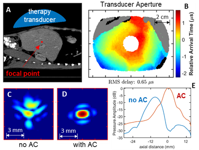
Fig. 3: Acoustic simulation of histotripsy targeting a point in the liver. A) Geometry of the simulation using a segmented human CT. B) Estimates of arrival time delays projected onto the face of the therapy transducer. Field map of the focal zone without aberration correction (C) and with aberration correction (D). Line plots of pressure amplitude with and without aberration correction showing an increased output of 6 dB and elimination of focal shift (E).
Cavitation Localization and Mapping
Numerous active methods for localizing and mapping cavitation during histotripsy, including standard B-mode ultrasound imaging and passive acoustic mapping (PAM), have been previously been demonstrated. However, these methods are often limited by obstructions in the imaging path (e.g., skull or ribs) and are only capable of localizing cavitation, particularly in 3D, at rates on the order of 10 Hz to 50 Hz, which is well below the histotripsy pulse delivery rates used clinically, ≥100 Hz. Our lab has developed novel methods to address the limitations associated with prior methods by using transmit-receive capable histotripsy systems to measure the shockwave acoustic cavitation emission (ACE) signals generated during histotripsy cavitation bubble nucleation and collapse [5]. First, a 500 kHz, 256-element hemispherical, transmit-receive capable histotripsy array was used to generate cavitation in excised bovine brain tissue through excised human skulls and acquire the resulting ACE signals associated with cavitation nucleation. The collected ACE signals were then back-projected into the field and used to identify their locations. Results showed that cavitation could be localized in this fashion at rates up to ~70Hz and that the cavitation localization was accurate to within 1.43+/-0.76 mm (Fig. 4, left). Further, the maps of detected cavitation bubble generation agreed well with the generated damage observed in the treated brain samples (Fig. 4, right).
Figure 4: Top) Projected map of cavitation events generated in the bovine brain sample based on the measurements of the ACE signals using the elements of the 500kHz array as receivers. Bottom) Image of the lesion generated in the bovine brain sample during treatment; the shape of the lesion agrees well with the map of detectable cavitation events shown in the localization heat map.
In another set of experiments, a 700 kHz, 360-element hemispherical, transmit-receive capable transducer was used to deliver treatment to the brains of human cadavers (<96 hours post mortem), and the array elements were used to collect the ACE signals and monitor the location of the generated cavitation; after treatment, MR images of the cadaver brains were acquired to evaluate the location of the generated ablation zones for comparison with the acoustic localization results. In this study, the ACE signals associated with cavitation collapse (as opposed to nucleation) were used to evaluate the location of cavitation. In particular, cavitation during histotripsy is nucleated as a cloud of tens to hundreds of individual, tightly packed microbubbles, each of which emits their own shockwave signal, and can thus require extensive signal processing to localize. As the bubbles within the initial cloud grow, however, they coalesce into a single bubble which emits only a single shockwave signal upon collapse. This, in turn, allows the bubbles to be localized using simplified, less computationally expensive time-domain methods including trilateration ACE (TRACE) and backwards transmit-delay ACE (backTRACE) [5,6]. Figure 5 (top) shows a series of plots highlighting the ACE signals and signal processing steps used to localize cavitation using the backTRACE method during these studies. Results showed that we could localize cavitation in the cadaver brains using these methods at rates up to 125Hz, and further analyses indicate that rates up to 250Hz are possible. Localization results were accurate to within 3.9mm of the observed ablation zones in the brains, however, retrospective analyses indicated that there was a 2.5mm error in the registration between the cadaver head and the histotripsy array and subsequent testing indicated accuracy on the order of 1.5mm is achievable. Nevertheless, the locations of the generated cavitation events based on the ACE signals were in good morphological agreement with observations of the ablation zone in the post treatment MRI (Fig 5, bottom-right).
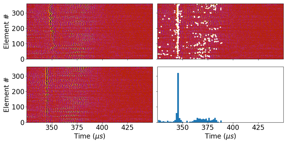
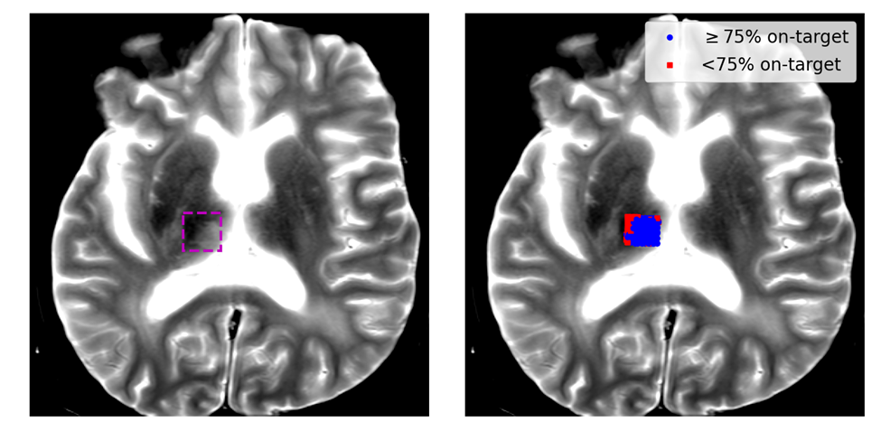
Figure 5: Top) a series of plots showing the signal processing steps to rapidly localize cavitation using the ACE signal associated with cavitation collapse. upper-left: raw cavitation signals acquired using the array elements through the cadaver skull. lower-left: ACE signals phase aligned to highlight the collapse ACE signals. Upper-right: the detected peaks (white dots) in the observed ACE signals. lower-right: a histogram of the time-of-arrivals of the detected peaks in the signals; a singular peak indicates on target cavitation generation. Bottom) MR images of the lesion generated in the cadaver brain; a plot of the detected on-target cavitation events is overlaid on the MR image in the right-hand figure.
Histotripsy Tissue Damage Monitoring
One of the biggest challenges associated with histotripsy is determining the amount of damage generated by cavitation to ensure complete ablation of the targeted tissue is achieved. Establishing such a metric is a challenge because the histotripsy parameters required to completely ablate tissues are highly dependent on the tissues mechanical properties [8,9], which vary with different tissue types, and between patients, and can be difficult to predict in advance of treatment. Our group has worked on developing methods to use the acoustic cavitation emission signals from the generated bubbles in order to assess the level of induced damage generated during treatment. In particular, the dynamics of cavitation bubbles, and thus the shockwave signals emitted by them, are known to be impacted by the material properties of the media in which they are generated. During a given histotripsy treatment, a tissue will start out as an initially intact viscoelastic ‘solid’, but over the course of treatment will be reduced to a viscous acellular liquid-like homogenate. As the material properties of the tissue will change during treatment, it is reasonable to expect that the dynamics of the generated bubble, and thus the ACE signals, will change as well. Once a tissue has been fully homogenized, its material properties will reach a steady state and so will the ACE signals. By monitoring for changes in the ACE signals until they reach a steady state, the damage state of the target tissue can be assessed.
Our lab has performed experiments in both viscoelastic, tissue mimicking hydrogels and excised tissue samples to identify how the ACE signals change as a function of histotripsy exposures and how the changes correlate with the level of induced damage. In both hydrogels and tissues (Fig. 6) we have shown that the timing between the ACE signals associated with cavitation nucleation and collapse (i.e., the cavitation lifespan) increases with increasing levels of cavitation exposure, and eventually reaches a plateau state when the material has been fully destroyed [7]. Recent investigations in a more diverse sets of hydrogels and tissues have also indicated that the ways in which the ACE signals change throughout treatment is dependent on the structure of the nucleation medium in addition to its material properties (Fig. 7) and suggests that multiple features of the ACE signals, including their amplitudes and energies may also need to be monitored to determine the level of damage generated within them [6].
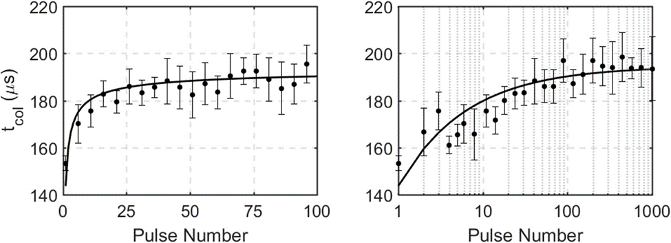
Figure 6: Hydrophone-measured cavitation lifespan for the first 100 histotripsy pulses (left, linear scale) and 1000 pulses (right, log scale) applied to ex vivo bovine liver (n=4). The majority of the change in bubble lifespan is observed in the first 100 pulses, with little to no change between pulse 100 and pulse 1000.
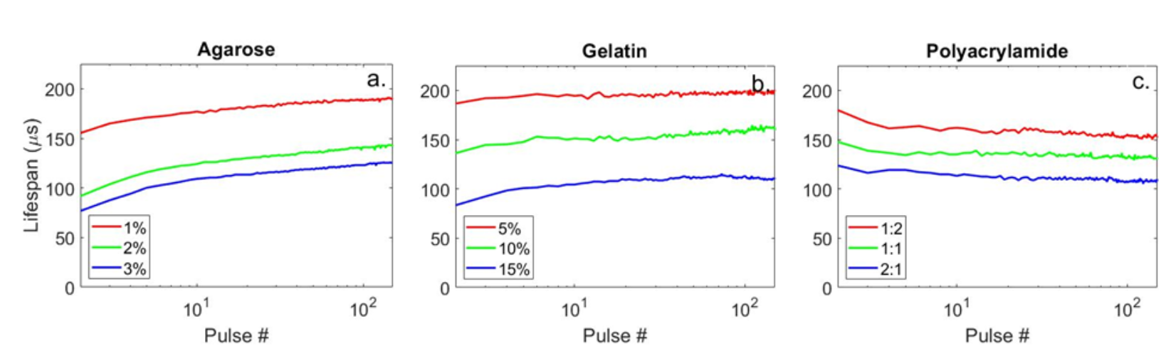
Figure 7: Plots showing the cavitation lifespans as a function of cavitation exposure count in different hydrogels. Note that in the agarose and gelatin hydrogel samples (left & middle) the cavitation lifespan increases monotonically as observed in the ex vivo bovine liver tissue (Fig. 6), but in the polyacrylamid gel (right) the cavitation lifespan follows an opposite trend and descreases throughout treatment.
References
[1] Gateau, J., Marsac, L., Pernot, M., Aubry, J. F., Tanter, M. & Fink, M. Transcranial ultrasonic therapy based on time reversal of acoustically induced cavitation bubble signature. IEEE transactions on bio-medical engineering 57, 134-144, (2010). 3081822
[2] Lu, N., Hall, T. L., Sukovich, J. R., Choi, S. W., Snell, J., McDannold, N. & Xu, Z. Two- step aberration correction: application to transcranial histotripsy. Phys. Med. Biol. 67, (2022).
[3] Yeats, E., Gupta, D., Xu, Z. & Hall, T. L. Effects of phase aberration on transabdominal focusing for a large aperture, lowf-number histotripsy transducer. Phys. Med. Biol. 67, (2022).
[4] Yeats, E., Lu, N., Sukovich, J. R., Xu, Z. & Hall, T. L. Soft Tissue Aberration Correction for Histotripsy Using Acoustic Emissions From Cavitation Cloud Nucleation and Collapse. Ultrasound Med Biol 49, 1182-1193, (2023). PMC10082475
[5] Sukovich, J. R., Macoskey, J. J., Lundt, J. E., Gerhardson, T. I., Hall, T. L. & Xu, Z. Real- Time Transcranial Histotripsy Treatment Localization and Mapping Using Acoustic Cavitation Emission Feedback. IEEE Trans Ultrason Ferroelectr Freq Control 67, 1178- 1191, (2020).
[6] Haskell, S. C., Lu, N., Stocker, G. E., Xu, Z. & Sukovich, J. R. Monitoring cavitation dynamics evolution in tissue mimicking hydrogels for repeated exposures via acoustic cavitation emissions. J Acoust Soc Am 153, 237, (2023). PMC10162839
[7] Macoskey, J. J., Choi, S. W., Hall, T. L., Vlaisavljevich, E., Lundt, J. E., Lee, F. T., Johnsen, E., Cain, C. A. & Xu, Z. Using the cavitation collapse time to indicate the extent of histotripsy-induced tissue fractionation. Phys. Med. Biol. 63, 055013, (2018).
[8] E. Vlaisavljevich, Y. Kim, G. Owens, W. Roberts, C. A. Cain, and Z. Xu, “Effects of tissue mechanical properties on susceptibility to histotripsy-induced tissue damage,” Physics in Medicine & Biology, vol. 59, no. 2, p. 253, 2013.
[9] E. Vlaisavljevich, A. D. Maxwell, M. Warnez, E. Johnsen, C. A. Cain, and Z. Xu, “Histotripsy-induced cavitation cloud initiation thresholds in tissues of different mechanical properties,” IEEE transactions on ultrasonics, ferroelectrics, and frequency control, vol. 61, no. 2, pp. 341–352, 2014.